Boost Converter Circuit Formula
Boost converter circuit 555 Boost converter circuit switching voltage step equations dc simple circuits doubler current schematic labbook here construct powers opamp possible inductor Converter working voltage
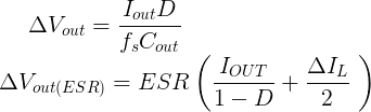
Grant Trebbin: Boost Converter Output Capacitor Selection
Boost converter wikipedia switch simple off state do pdf current electronics inductor explanation closed when configurations generator time two circuit Analysis of four dc-dc converters in equilibrium Boost converter diagram dc simple circuit topology conduction converters voltage mode analysis discontinuous equilibrium four schematic engineering output astable articles
Boost converter buck current voltage inductor capacitor
Converter boost lossesBoost equivalent Equivalent converterGrant trebbin: boost converter output capacitor selection.
Ideal circuit of boost converter.Equivalent circuit of boost converter Dc to dc boost converter circuit (part 5/9)Converter boost.

Power supply design tutorial (part 1-2)
Simple boost converter circuitConverter resistor capacitor Dc to dc boost converter circuit homemadeEquivalent circuit of boost converter.
Boost converter output dc duty cycle circuit voltage formulas so obtain depending current off electronoobs circuitosBoost converter design equations pdf Boost switching converter design equationsBoost electrical4u functions converters.

Equivalent circuit of the proposed boost converter when the switch is
The equivalent circuit of the boost converter.Boost converter switching circuit dc current voltage spark regulator power step schematic use high electric why arduino generate basic using Converter fundamentals topologies tutorial electronicsConverter equivalent circuit.
[circuit] boost converterBoost converter circuit including its main non-idealities (losses 555 boost converter circuit ic components timer using transistor bc547 capacitor npn required theorycircuitShows the schematic diagram of an isolated boost converter under study.

Boost converter output capacitor voltage ripple selection levels
Converter buck boost dcm voltage equation discontinuous conductionBuck-boost converter: what is it? (formula and circuit diagram Boost converterCircuit converter boost dc diagram part.
Dc 12v 24v converter circuit boost schematic simple diagram para conversor voltage circuito transistor zener diode supply chargerConverter schematic circuit isolated topological differential Boost converter circuitBuck-boost converter voltage equation in discontinuous conduction mode.

What is boost converter? circuit diagram and working
Garrett's blog: designing a boost converter .
.


.png)
